

Fire stopping is often described as a finishing trade, but in real buildings it behaves more like a structural safety system. If the compartment line is broken by an unsealed service penetration, a poorly packed joint, or the wrong insulation density, fire and smoke will move where the design never intended. That is why fire stop insulation specifics matter: they determine whether the fire resistance rating of a wall or floor is preserved after every cable tray, pipe run, and last-minute change.
This article sets out the fire stop insulation specifics that typically decide pass or fail on inspection, including what to specify, how to install, and what to document. It is UK-focused and aligned to the standards and best-practice guidance commonly referenced by competent contractors and inspectors.
Fire stop insulation specifics start with compartmentation, not products
Before selecting any sealant, batt, or collar, define the function you are trying to protect. Most passive fire protection is built around compartmentation: splitting the building into zones that resist fire and smoke spread for a defined period. Penetrations and joints are the weak points, so the job of fire stop insulation is to reinstate the performance of the separating element after it has been cut or built in stages. Promat’s technical guidance summarises the principle clearly: boundaries between compartments must prevent fire and smoke penetration, which is only achieved by installing appropriate fire stopping systems.
From this viewpoint, fire stop insulation specifics are less about brand selection and more about matching a tested system to the exact wall or floor build-up, service type, and gap geometry.
What is included under fire stopping in best-practice guidance
A reliable starting point for scope is the ASFP on-site guidance, which defines fire stopping as including cavity barriers, penetration seals for services, and linear joint seals. It also stresses that manufacturers’ instructions take precedence and that installation competence is essential.
That scope gives you the three main families of work where fire stop insulation specifics should be documented:
- Penetration seals, such as pipes, cables, ducts, and combined service openings
- Linear joint seals, such as head of wall, perimeter gaps, and movement joints
- Small cavity barriers, such as void closers and concealed cavity protection
Each family is tested differently and has its own failure patterns.
The standards language you will see in fire stopping documentation
Fire stopping is typically supported by fire resistance tests and classifications, and it helps to recognise the core terms.
EI ratings and classification. Fire resistance performance is commonly expressed using criteria such as integrity and insulation, which appear in EI classifications. UK building regulations guidance references the use of BS EN 13501 classification routes for fire resistance.
Test standards you will see on data sheets. For service penetrations, the relevant testing framework is typically BS EN 1366-3 for penetration seals. BSI describes BS EN 1366-3 as a test method for assessing the contribution of a penetration seal to the fire resistance of separating elements.
For linear joints, BS EN 1366-4 is the commonly referenced standard for linear joint seals.
A note on legacy BS 476 evidence. Some projects still encounter BS 476 test evidence. BSI’s overview explains the BS 476 series and its changing status as the UK continues to align with European norms.
The practical point is not to debate standards on site, but to ensure the chosen system has evidence accepted by the project team, building control, and the fire strategy.
These references are part of the fire stop insulation specifics you should expect in submittals and handover packs.
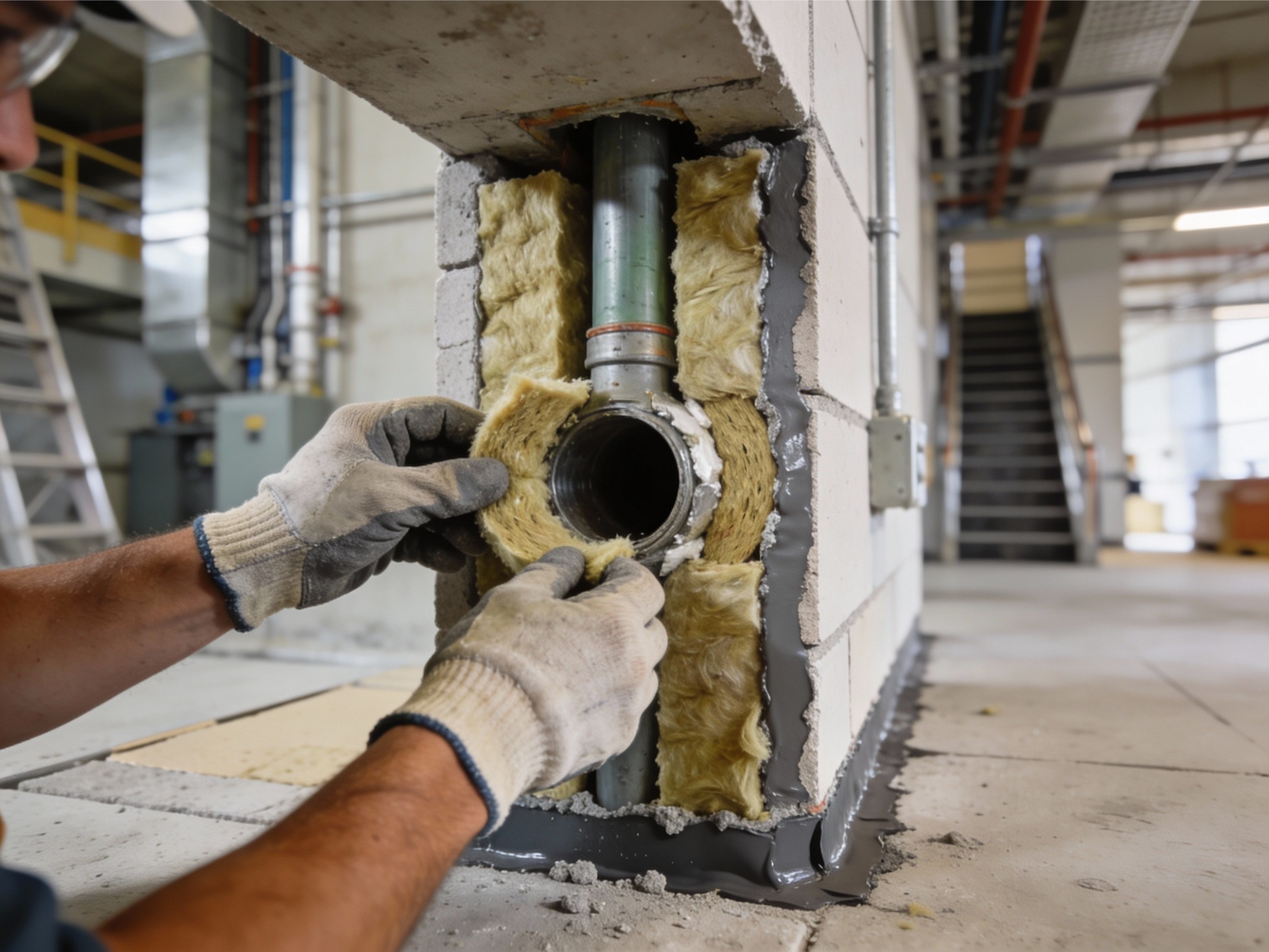
Fire stop insulation specifics by system type
1) Penetration seals: the service penetration fire stopping reality
Penetration seals are where buildings most often lose compartment integrity because the volume of services changes throughout the programme. The fire stop insulation specifics that matter here are:
- Substrate type and thickness: masonry, concrete, plasterboard, flexible wall, raised floor
- Service type: metallic pipe, plastic pipe, insulated pipe, cable bundle, cable tray, mixed services
- Annular gap and opening size: measured, not guessed
- Required performance: time rating and whether insulation performance is required on one side or both
- System selection: must be tested for that substrate and service configuration (including insulation type and thickness on the pipe where relevant)
A common insulation-based penetration method is the ablative coated mineral wool batt, sometimes called a fire batt. Rockwool describes its ablative coated batt as a stone wool core pre-coated with an ablative layer, tested to provide up to 240 minutes subject to application.
This is a useful example of why fire stop insulation specifics must include application conditions. A batt system can be robust, but only when installed to the tested detail: correct batt thickness, correct coating orientation, correct perimeter sealing, and compatible sealants.
2) Linear joint seals: head of wall, slab edge, and movement
Linear joints look simple, but they are high-risk because buildings move. Drying shrinkage, deflection, thermal movement, and differential movement all stress seal lines.
The fire stop insulation specifics for linear seals should include:
- Joint width range the system is tested for
- Whether movement is expected and in which direction
- Backing material specification, often mineral wool of a stated density and compression fit
- Sealant depth, bead geometry, and finishing requirements
- Fixing methods for boards or curtain wall interfaces where relevant
The EN 1366-4 test regime exists because joints behave differently to penetrations, including movement conditions.
This is why a generic bead of sealant is rarely acceptable as a fire stopping solution unless it is part of a tested linear joint seal system.
3) Cavity barriers and small cavity barriers: stopping hidden fire spread
Cavity barriers are often forgotten until late, then installed under pressure. Yet they are fundamental to preventing concealed fire spread in voids and external wall cavities.
The key fire stop insulation specifics here are correct location, continuity, fixing method, and compatibility with ventilation requirements and moisture design. Even small gaps and discontinuities can undo the intended line of protection.
Materials and components: what you are actually installing
Fire stop insulation is often a combination of insulation and a closure layer. Typical components include:
- Mineral wool slabs or lamella, used as backing or packing in joints
- Ablative coated batts or boards for service openings, usually sealed to the substrate
- Intumescent acrylic or silicone sealants for linear gaps and perimeter seals
- Intumescent collars or wraps for combustible pipes
- Fire sleeves and pipe closures for specific pipe types
- Fire pillows or modular blocks for openings that must remain accessible
- Fire-rated foams, used only where the system evidence supports their use
When combining these components, considering their flame spread classification helps verify suitability for exposed surfaces in compartment boundaries. Intumescent sealants and mastics are widely used as part of tested linear joint and penetration seal systems.
The technical risk is mixing components that have never been tested together. fire stop insulation specifics should always include compatibility statements from the manufacturer system evidence, not site assumptions.
Fire stopping details you must specify, not leave to chance
Most installation defects are not exotic. They are predictable outcomes of missing information. The fire stopping details that should appear in drawings, schedules, or contractor proposals include:
- Exact location of the compartment line and which penetrations cross it
- Approved system reference for each service type and substrate
- Permitted opening size and annular gap range
- Insulation type, density, and required compression fit
- Sealant type, bead geometry, and depth
- Requirements for face-fixed plates, sleeves, or reinforcement
- Required labelling and photographic evidence at handover
- Rules for later modifications, such as adding cables to a sealed opening
This is one of the most operationally important fire stop insulation specifics: if you cannot describe it, you cannot inspect it.
A practical fire stopping guide: installation workflow that holds up on inspection
Use the sequence below as a site-ready fire stopping guide that aligns with ASFP best-practice concepts and manufacturer-first installation principles.
1) Survey and record the opening. Measure the opening size and confirm substrate type and thickness. Identify the services, including pipe insulation, cable grouping, and any planned future capacity.
2) Select a tested system for that exact configuration. Match service, substrate, and gap size to a tested and classified system. For penetrations, look for evidence aligned to EN 1366-3.
For linear joints, look for EN 1366-4 evidence.
3) Prepare the substrate properly. Remove dust, laitance, and loose materials. Fire stopping fails when it is bonded to contamination rather than structure.
4) Install insulation to the specified fit and depth. Mineral wool must be cut accurately and installed to the required compression. Gaps behind the packing are common hidden defects.
5) Apply closure layers exactly as tested. For example, apply ablative coating orientation correctly, apply sealant depth and bead geometry as specified, and ensure continuity around the full perimeter.
6) Label and photograph. Labelling is not cosmetic. It ties the installed detail to the tested system reference and helps future trades avoid destructive alterations.
7) Manage changes. If services change after completion, the opening must be re-evaluated and resealed using an appropriate system, not patched with whatever is in the van.
This workflow is part of the fire stop insulation specifics that make a building maintainable, not just inspectable.
Inspection and documentation: proving the compartment line is reinstated
The ASFP provides technical documents and a code of practice focused on installation and inspection of fire stopping systems, covering linear joint seals, penetration seals, and small cavity barriers.
In practice, inspection should verify:
- Correct system used for the correct substrate and service type
- Clean, tight installation with continuity at perimeters
- No visible voids, cracks, or unsealed edges
- Proper support and fixing where required
- Evidence pack completeness: system references, photos, installer details, and location identifiers
If you treat inspection as an afterthought, defects will be hidden behind ceilings and riser doors until the first intrusive audit.
Common defects and how to prevent them
The same problems appear across new build and refurbishment projects:
- Oversized openings that fall outside the tested annular gap range
- Wrong mineral wool density or insufficient compression fit
- Sealant bead too thin, too shallow, or broken by movement
- Mixed systems, such as a batt from one range with a sealant from another
- Plastic pipe penetrations treated like metal pipe penetrations
- Later cable additions pushed through without reworking the seal
These failures are avoidable when fire stop insulation specifics are controlled through a schedule, a trained installation team, and an evidence-based inspection routine.
Conclusion: treat Fire stop insulation specifics as a system, not a filler
Fire stop insulation is one of the few building elements that is repeatedly disturbed over the building’s life. Every new data cable, new pipe run, or altered riser layout can compromise the compartment line. That is why fire stop insulation specifics should be documented, inspected, and managed like any other life-safety system.
If you take one message from this article, let it be this: use tested systems, follow manufacturer instructions, and insist on clear fire stopping details and evidence at handover. With that approach, this becomes a repeatable fire stopping guide your teams can apply consistently across walls, floors, risers, and voids, long after the original contractor has left site.