

In a developing fire, heat is frightening, but smoke is often what turns a manageable escape into a blind, toxic rush. That is why smoke ventilation is treated as a life-safety system, not a nice-to-have add-on. This AOV ventilation guide explains how an Automatic Opening Vent (AOV) is meant to perform, where it belongs in a building’s fire strategy, and what separates a compliant installation from a vent that looks correct but fails when it matters.
If you manage a residential block, design common corridors, or maintain a mixed-use building, the goal is consistent: keep escape routes tenable for long enough to evacuate and support firefighting access. A well-specified AOV helps by releasing smoke and heat at high level, reducing smoke logging in stairs and lobbies, and improving visibility where people need it most. This AOV ventilation guide focuses on natural smoke ventilation using AOVs, while also explaining when mechanical smoke control is the more appropriate route.
What an AOV actually does in a fire scenario
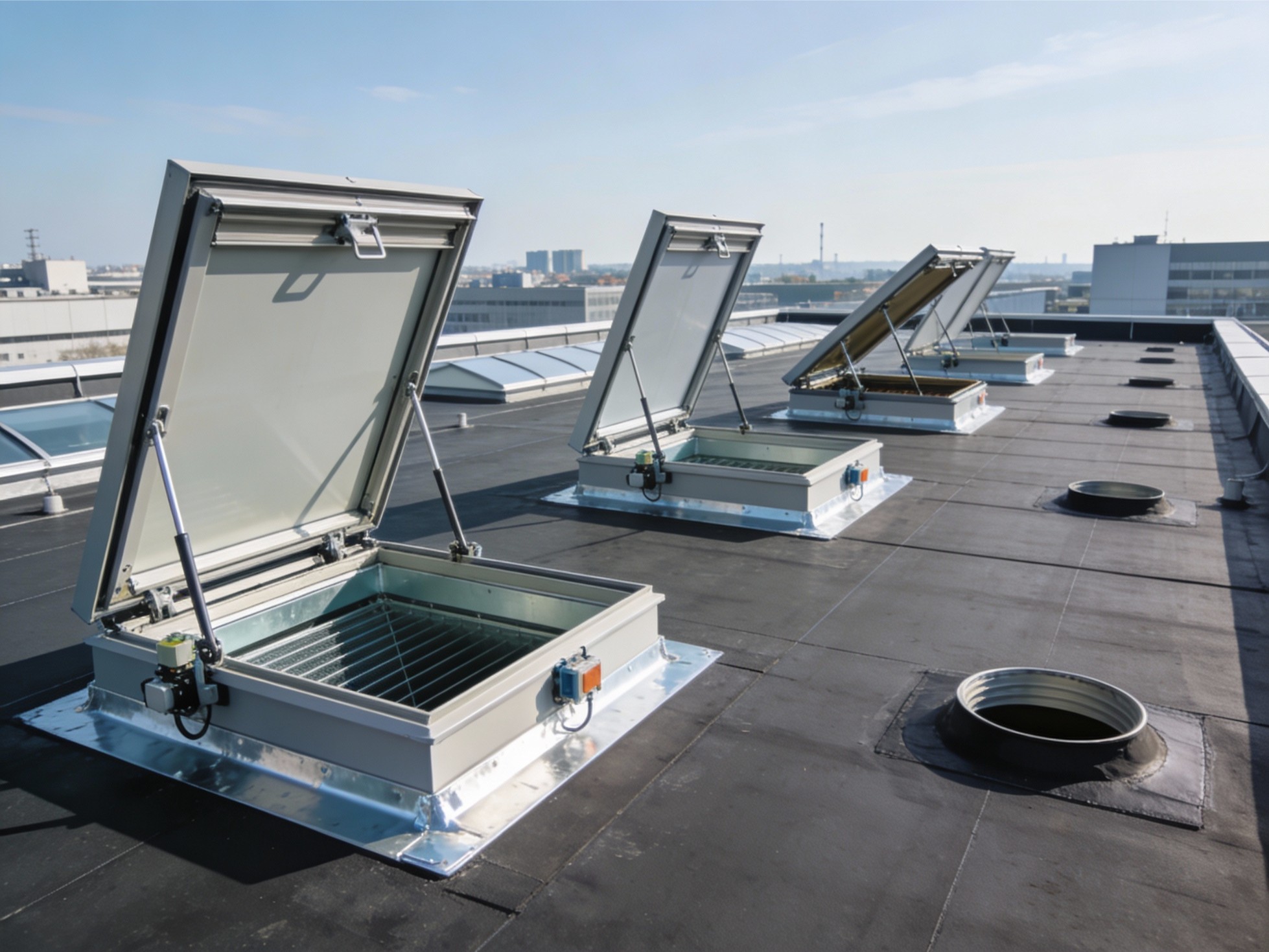
An automatic opening vent is a powered ventilator, usually a roof vent, façade vent, or louvre, that opens on a fire signal to let smoke exhaust naturally. You will also see AOVs discussed under the wider umbrella of Smoke and Heat Exhaust Ventilation (SHEV) or Natural Smoke and Heat Exhaust Ventilators (NSHEVs). In practice, the vent is only one part of a complete smoke control approach: it must be sized correctly, placed correctly, and controlled correctly.
The critical idea is simple: smoke rises and pools at high level. Venting at the correct high-level location provides a preferential path for smoke to leave the enclosure, while replacement air enters elsewhere. That pressure and flow balance is why the opening size and the availability of make-up air matter as much as the actuator.
UK product and system expectations are typically referenced to the EN 12101 family for smoke and heat control equipment, with EN 12101-2 specifically addressing natural smoke and heat exhaust ventilators.
Typical locations: stair cores, corridors, and smoke shafts
AOVs are most commonly associated with communal stairs and lobbies in multi-storey residential buildings, where smoke control is used to protect the common stair. The common pattern is:
- A vent at the top of the stair to exhaust smoke at the highest point.
- A vent in the corridor or lobby next to the stair to release smoke from the fire floor while the stair is kept clearer.
- In taller or more constrained layouts, vents may discharge into a vertical smoke shaft rather than straight to outside.
In these contexts the aov smoke vent is doing one job: supporting the means of escape by limiting smoke spread and reducing smoke density in the shared route. The same principles can also apply to firefighting lobbies and some non-residential arrangements, but the design logic should always come from the building’s fire strategy, not a generic template.
AOV building regulations and the standards that sit behind them
People search for aov building regulations because they want a single rule to follow. In reality, compliance is achieved by aligning the smoke control design with statutory guidance and appropriate standards, then proving that the installed system performs as intended.
For England, Approved Document B provides explicit guidance on smoke control to common escape routes in blocks of flats. It sets out the need for smoke ventilation to corridors or lobbies next to each stair, specifies placement at high level, and gives minimum free area values for vents.
Approved Document B Volume 1 includes practical benchmarks that are widely used in residential designs, including:
- A corridor or lobby smoke vent next to each stair, placed as high as practicable with its top edge at least as high as the top of the stair door.
- A vent on an external wall with a minimum free area of 1.5 m², or discharge into a properly designed smoke shaft meeting stated criteria.
- A vent to the outside with a minimum free area of 1 m² from the top storey of the stair.
- Activation logic in single-stair buildings using smoke detectors in common parts to open the relevant vents.
Alongside this, the EN 12101 suite provides performance and testing frameworks for smoke control components (natural vents, fans, control panels, power supplies). AOV building regulations therefore becomes less about one paragraph and more about demonstrating that the system chosen meets the functional requirement: keeping escape routes usable long enough to evacuate.
For planning, handover, and lifecycle obligations, BS 7346-8 is frequently referenced as the code of practice covering planning, design, installation, commissioning, and maintenance of smoke control systems.
The design fundamentals that decide whether the system works
A good AOV ventilation guide should be clear about the fundamentals that drive outcomes. These are the decisions that determine whether your smoke control is credible.
1) Start with the fire strategy, not with the product
The vent arrangement must match the building’s intended evacuation strategy, stair arrangement, corridor geometry, and compartmentation. If the project has a fire engineer, follow the smoke control calculations and interface requirements. If it does not, that is a risk in itself, because smoke ventilation is performance-led even when minimum guidance values exist.
2) Free area is not the same as the visible opening
Approved Document B speaks in terms of free area. AOV performance discussions often include aerodynamic free area, which accounts for how effectively smoke can flow through the opening (including the effects of blades, grilles, and geometry). This is why measuring and declaring free area correctly matters, and why manufacturers publish free area data for their ventilators.
Manufacturers and specialist guidance also highlight that free area measurement has specific interpretations for windows and louvres, and it must match the regulatory intent.
3) Location and smoke layer behaviour
Smoke vents must be high level because smoke layers form near ceilings first. A vent placed too low, behind deep reveals, or obstructed by architectural features will underperform even if the free area is technically adequate.
4) Make-up air and pressure balance
No smoke exhaust works in isolation. If the vent opens but the building cannot admit replacement air, airflow stalls and smoke can spread unpredictably. Make-up air may be provided by door clearances, dedicated inlets, automatic door releases, or other designed openings depending on the strategy.
This is also where design errors appear: a vent sized to guidance, but no clear route for air to enter, resulting in poor smoke clearance.
What makes up an AOV system in practice
AOVs are often described as a vent and an actuator. In reality, an aov system is an integrated set of components that must operate together:
- Ventilator: roof vent, façade vent, or louvre configured for smoke exhaust.
- Actuator or opening mechanism: electrical, pneumatic, or other certified method depending on application.
- Controls: AOV control panel, interfaces, and cause-and-effect logic.
- Power: mains supply plus monitored standby (commonly battery-backed).
- Initiation: smoke detectors in common parts, fire alarm interface, and manual triggers.
- Overrides: fire service switches, break-glass points, and reset functions where required.
The standards framework emphasises that smoke and heat control is a system, with EN 12101 covering multiple component categories and their roles.
Installation and commissioning: a practical workflow
This section is the most operational part of the AOV ventilation guide, because many failures are born in the final 10 percent of the job.
1) Pre-install checks that prevent expensive rework
Before installation begins, verify:
- The fire strategy and the correct vent locations for stair head and corridor/lobby.
- The specified free area values and whether the selected ventilator achieves them in its fire-open position.
- Structural openings, kerbs, upstands, weathering details, and fall protection considerations.
- Cable routes, fire-resisting cable selection where required, and segregation from other services.
2) Fit-out of the aov smoke vent and actuator
For roof units, installation quality often hinges on the kerb and weathering. For façade vents, alignment, hinges, and opening geometry must be checked carefully. The vent must open to the designed angle without binding, and it must not foul against cladding, reveals, or security grilles.
3) Controls, interfaces, and cause-and-effect logic
Commissioning is where the aov system becomes real. You need a documented cause-and-effect matrix that shows:
- Which detector zones or signals open which vents.
- Whether vents on non-fire floors remain closed where required for the strategy (for example, smoke shaft logic often depends on only the fire floor opening).
- Manual override behaviour for building staff and firefighters.
- Fault monitoring and fail-safe states (such as loss of mains power).
4) Functional tests and handover evidence
At minimum, verify:
- Correct vent opening on automatic signal.
- Manual trigger operation.
- Full opening within expected time and to the intended fire position.
- Confirmation that vents are not obstructed and that make-up air paths are available.
BS 7346-8 is widely used as the lifecycle reference point for planning, commissioning, and maintenance expectations.
Maintenance and inspection: keeping smoke ventilation dependable
AOVs fail quietly. They are not used every day, which means faults accumulate unnoticed until the moment a fire signal arrives. This AOV ventilation guide recommends treating routine checks as non-negotiable.
At a practical level, maintenance should include:
- Visual inspections for obstruction, corrosion, damage, or tampering.
- Functional tests to confirm the vent opens fully and the controls respond correctly.
- Inspection of batteries, power supplies, and fault logs at the control panel.
- Verification that detectors and manual triggers are still in place and operational.
Industry guidance for smoke control equipment maintenance commonly recommends periodic inspection and maintenance intervals (including six-monthly servicing in many cases) to identify unmonitored faults and maintain reliability.
If the building has a formal fire risk assessment regime, maintenance records should be integrated into that management system. The paper trail is not bureaucracy; it is evidence that the system was ready to perform.
Common problems that undermine performance
Even well-intentioned projects can create an AOV that is technically present but practically compromised. The patterns below are common.
- Painted shut or sealed: especially in refurbishment cycles.
- Obstructed by later works: ceiling changes, signage, security grilles, or stored items near vents.
- Incorrect free area assumption: a window may look large but deliver less effective free area once opening angle and geometry are considered.
- Poor interface logic: vents open on the wrong floors, or multiple openings create adverse flow.
- Neglected batteries: standby supplies degrade over time and must be tested and replaced to specification.
If you are repeatedly dealing with call-outs for unexplained faults, that is often a symptom of weak handover documentation rather than a single defective component.
Selecting the right solution and contractor
Because aov building regulations are performance-led, competence matters. The key selection criteria should include:
- Evidence of compliant product performance (such as documentation aligned with EN 12101-2 for natural smoke vents).
- A commissioning process that includes cause-and-effect documentation and functional test records.
- Clear maintenance proposals, inspection intervals, and logbook templates.
For building owners and managing agents, the handover pack should be treated like the fire door certification pack: it is part of the building’s safety case in practice, even when the system sits quietly overhead.
Bringing it together
A smoke vent that opens is not automatically a compliant smoke control solution. The difference is whether the design, installation, and ongoing management align with guidance and standards, and whether the system will work under stress.
This AOV guide can be summarised into a simple checklist:
- Use Approved Document B benchmarks for vent placement and minimum free area where applicable, and validate against the building fire strategy.
- Treat the aov system as an integrated life-safety package: vent, actuator, controls, power, initiation, and overrides.
- Commission properly with documented cause-and-effect logic and recorded tests.
- Maintain proactively, because failure is usually silent until the emergency arrives.
If you want a site-specific review, the fastest route is to map your stair and corridor layout, confirm vent free areas, and audit the existing activation logic. That is how an AOV ventilation guide becomes a working safety system rather than a line item on a specification.